


4 - 2
TM
CHAP. 4
TECHN…
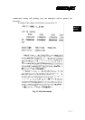
CIRCUITRY LAYOUT & CONNECTORS
U1
CN2
CN1
7
8
6
5
4
3
2
1
EDG
ON
ON
EDG
1
2
3
4
5
6
8
7
ON
EDG
1
2
3
4
5
6
8
7
ON
EDG
1
2
3
4
U5
CN10
CN9
CN6
CN4
CN3
U11
SW1
SW2
SW3
SW4
CN5
CN8
CN11
JP15
U6
U8
JP5
U2
U3
JP1
JP2
JP14
U16
BZ1
JP4JP3
PST-PRT001A-TJ
BAT1
TMP90C041AF
M27C512
B303 6DAHG
SP232ACP
CN7
1
3
1
5
2
6
1
3
1
3
1
3
JP9
JP10
JP11
JP13
JP12
JP7
JP8
JP6
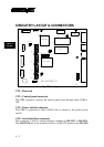
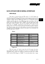
Fig. 17 Board layout
CN1 : Reserved
CN2 : Control panel connector
This CN2 connector connects the control panel board through cable CCBLA-
189.
CN3 : Power switch connector
This CN3 is connected to cable CCBLA-188 to connect to the printer power
switch.
CN4 : Serial interface connector
This connector is used to connect the host computer by RS-232C or RS-422A.
The MAX232A has to be installed in U3 to use RS-232 interface and MC3451