


5 - 3
TM
CHAP. 5
MAIN …
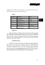
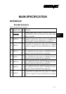
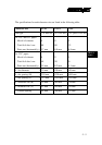
Serial Interface
9 pin Female D-sub connector
Pin
#
Signal Name I/O Function
1 DCD O Data carrier detect
2 TXD O Transmit data
3 RXD I Receive data
4 N.C.
5 GND Ground
6 RTS O
Request to send. This is always “SPACE” when the
printer is turned on.
7 N.C.
8 DTR O
Data terminal ready. This signal changes to
PACE” when the printer is ready to receive data.
9 N.C.
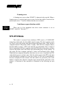
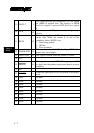
Peripheral Unit Drive
6 pin telephone jack
Pin
#
Signal Name I/O Function
1 Chassis GND
To connect the shield of cable between printer and
the peripheral device
2 L1 Drive O
Supplies a low trigger pulse to drive the circuitry L1
with a diode protection. This shall not be driven
together with L2 at the time.
3 SW Sense I
To connect through diode and resistor to +24VDC
to detect the status of cash drawer open detection
switch.
4 +24 V DC O Connected to +24VDC supplied by the printer.
5 L2 Drive O
Supplies a low trigger pulse to drive the circuitry L1
with a diode protection. This shall not be driven
together with L2 at the time.
6 GND O