


4 - 9
TM
CHAP. 4
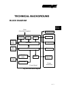
TECHN…
DATA STRUCTURE IN SERIAL INTERFACE
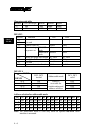
DTR Mode
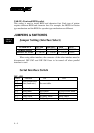
This mode is accessed when the DIP switch 1-5 is ON. Signals are
controlled using the DTR line as BUSY flag. If a printer errors do not occur after
the power is turned on, the DTR signal line changes to “SPACE”. When the host
computer confirms that the DTR signal line is set to “SPACE”, the host
computer sends the data text via the RXD signal line to the printer. Also, the
printer will set the DTR signal line to “MARK” when the empty space in the
data buffer is below 256 bytes. After the host computer detects that the DTR
signal line is at “MARK”, transmission of the data text is stopped. In this
instance, data can still be received up until the data buffer becomes completely
full. When the empty space in the data buffer is increased following printing
(when the data in the data buffer is reduced to 256 bytes or less), the printer sets
the DTR signal line to “SPACE”.
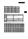
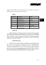
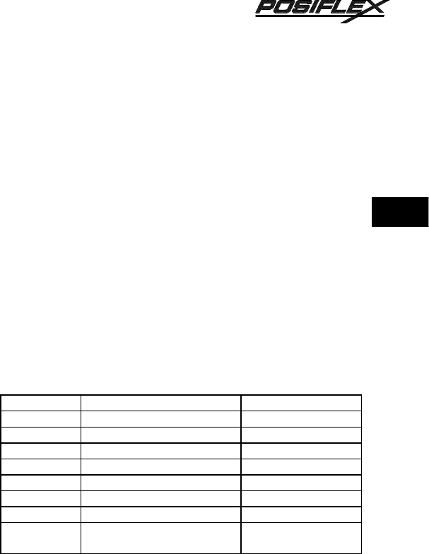
Status
Bit position Definition Level
b0 Vertical parity error 1:error
b1 Framing error 1:error
b2 Mechanical error 1:error
b3 Paper empty 1:empty
b4 Constantly set at “0” 0
b5 Buffer empty 1:empty
b6 Buffer overflow 1:overflow
b7
Cash drawer open detection
switch high level
switch is set to ON
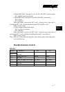
Paper out
When the “paper out” detector senses the end of the paper, the printer
stops printing after printing a maximum of two lines or on feeding the paper.
Immediately after a “paper out” condition is detected, the printer sets to “OFF
LINE” and the DTR changes to “MARK”. To reset the printer after a “paper