


Chapter 1 Description of the GPIB-BUF
© National Instruments, Corp. 1-3 GPIB-BUF User Manual
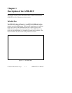
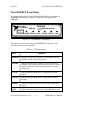
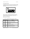
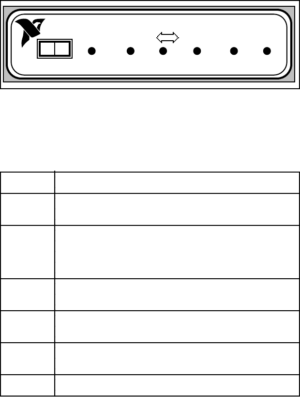
The GPIB-BUF Front Panel
The power switch and six Light Emitting Diodes (LEDs) are mounted on
the GPIB-BUF front panel. Figure 1-2 shows the front panel of the
GPIB-BUF.
GPIB-BUF
IEEE-488
IEEE-488 BUFFER
POWER READY TALK LISTEN EMPTY FULL
NATIONAL
INSTRUMENTS
Figure 1-2. The GPIB-BUF Front Panel
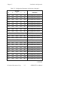
The LEDs show the current status of the GPIB-BUF at all times. The
following table describes each LED.
Table 1-1. LED Descriptions
LED Indication
POWER Indicates that power to the unit has been applied and the
ON/OFF switch is in the ON position.
READY Indicates that the unit is running its power-on self-test
(blinking), has passed its power-on self-test and is ready to
operate (steady on), or has failed the power-on self-test
(steady off).
TALK Indicates that the GPIB-BUF is configured as a GPIB
Talker.
LISTEN Indicates that the GPIB-BUF is configured as a GPIB
Listener.
EMPTY Indicates that the internal data buffer of the GPIB-BUF is
empty.
FULL Indicates that the internal buffer of the GPIB-BUF is full.