


Contents
GPIB-BUF User Manual viii © National Instruments Corp.
Appendix A
Hardware Specifications
..............................................................A-1
Appendix B
Customer Communication
..........................................................B-1
Glossary...............................................................................................G-1
Figures
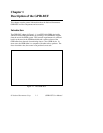
Figure 1-1. The GPIB-BUF ...................................................................1-1
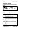
Figure 1-2. The GPIB-BUF Front Panel ................................................1-3
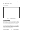
Figure 1-3. The GPIB-BUF Rear Panel .................................................1-4
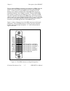
Figure 1-4. The GPIB Connector and Signal Designations ...................1-5
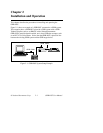
Figure 2-1. GPIB-BUF System Setup Example.....................................2-1
Figure 2-2. Factory Default Switch Settings..........................................2-4
Figure 3-1. Serial Poll Status Byte.........................................................3-5
Tables
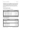
Table 1-1. LED Descriptions ................................................................1-3
Table 2-1. Configuration Parameters for Switches 1 through 3 ...........2-4
Table 2-2. Configuration Parameters for Switches 4 through 8 ...........2-5
Table 3-1. Parallel Poll Responses .......................................................3-7
Table A-1. Electrical Characteristics.....................................................A-1
Table A-2. Environmental Characteristics.............................................A-1
Table A-3. Physical Characteristics.......................................................A-2