


Installation and Operation Chapter 2
GPIB-BUF User Manual 2-4 © National Instruments Corp.
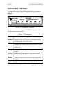
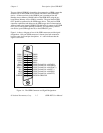
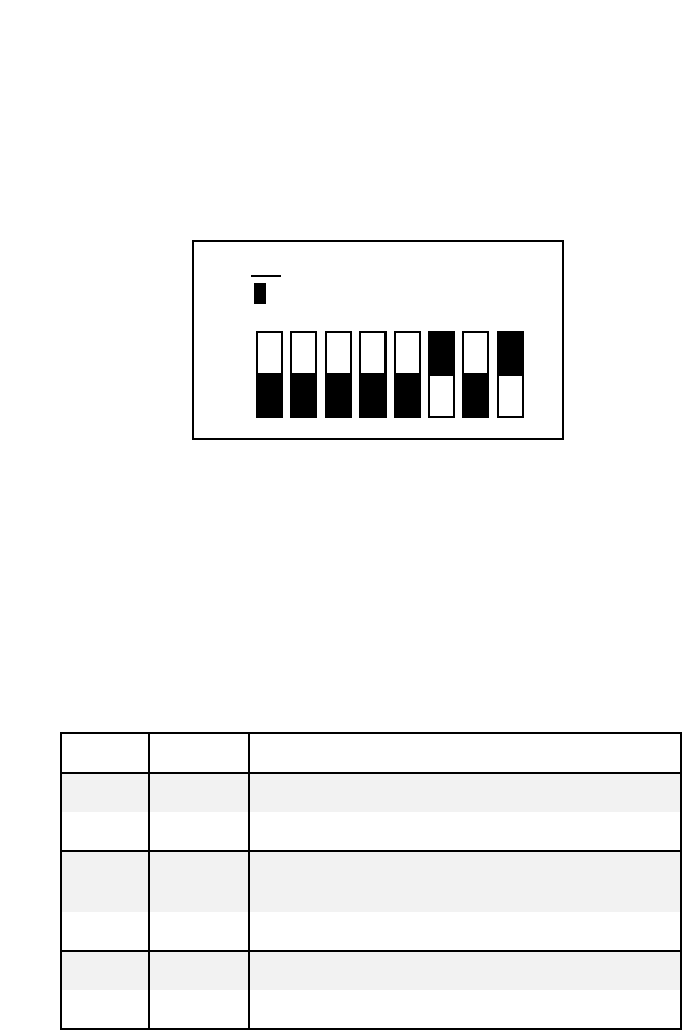
Set Configuration Switches
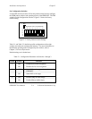
Use the DIP switch at location U38 on the printed circuit board to configure
the GPIB primary address and operating modes of the GPIB-BUF. The DIP
switch has eight configuration switches. Figure 2-2 shows the factory
default setting.
O
N
O
F
F
Key
= depressed side of switch handle
12345678
Figure 2-2. Factory Default Switch Settings
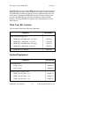
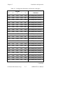
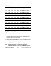
Table 2-1 and Table 2-2 detail the possible configurations of the eight
switches and what each configuration indicates. For more information on
the different operating modes configured by the switches, refer to
Chapter 3, Technical Information.
Default settings are in shaded rows.
Table 2-1. Configuration Parameters for Switches 1 through 3
Switch Position Indication
1 OFF Enables device clear recognition
ON Disables device clear recognition
2 OFF Sends DCL to the target and resets the
GPIB-BUF
ON Sends DCL to the target
3 OFF Disables SRQ on buffer empty
ON Enables SRQ on buffer empty