


Installation and Operation Chapter 2
GPIB-BUF User Manual 2-6 © National Instruments Corp.
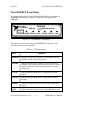
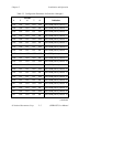
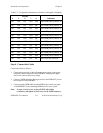
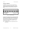
Table 2-2. Configuration Parameters for Switches 4 through 8 (Continued)
Switches
45678
Indication
ON OFF ON OFF OFF Sets GPIB primary address 20
ON OFF ON OFF ON Sets GPIB primary address 21
ON OFF ON ON OFF Sets GPIB primary address 22
ON OFF ON ON ON Sets GPIB primary address 23
ON ON OFF OFF OFF Sets GPIB primary address 24
ON ON OFF OFF ON Sets GPIB primary address 25
ON ON OFF ON OFF Sets GPIB primary address 26
ON ON OFF ON ON Sets GPIB primary address 27
ON ON ON OFF OFF Sets GPIB primary address 28
ON ON ON OFF ON Sets GPIB primary address 29
ON ON ON ON OFF Sets GPIB primary address 30
ON ON ON ON ON Sets listen-only operation
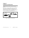
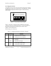
Step 4. Connect the Cables
Connect the cables as follows:
1. Connect the power jack of the wall-mount power supply to the power
receptacle on the back panel of the GPIB-BUF, then plug the supply
into an AC outlet of the correct voltage.
2. Connect a GPIB cable from the target device to the GPIB OUT port on
the rear panel of the GPIB-BUF.
3. Connect another GPIB cable from the GPIB IN port on the rear panel
of the GPIB-BUF to the remaining GPIB devices in your system.
Note: In steps 2 and 3, be sure to obey all IEEE 488 cabling
restrictions, and tighten all lock screws on the GPIB connectors.