


Description of the GPIB-BUF Chapter 1
GPIB-BUF User Manual 1-4 © National Instruments Corp.
The GPIB-BUF Rear Panel
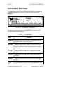
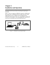
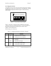
Figure 1-3 shows the power cable and the GPIB cables connected to the rear
panel of the GPIB-BUF.
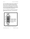
Figure 1-3. The GPIB-BUF Rear Panel
The GPIB Connectors
The GPIB-BUF has two GPIB connectors labeled GPIB IN and GPIB OUT.
Both GPIB connectors are standard 24-pin shielded AMP CHAMP female
connectors with metric screwlock hardware. As you face the rear panel, the
GPIB IN connector is the right-most GPIB connector. The GPIB OUT
connector is located on the left.
Notice that although these GPIB ports are labeled GPIB IN and GPIB OUT,
both are able to transfer data in either direction. The notations GPIB IN and
GPIB OUT are used in order to differentiate the ports since the GPIB IN
port, under normal circumstances, receives data while the GPIB OUT port
normally sends data to the GPIB target device.