


© National Instruments Corp. 2-1 GPIB-BUF User Manual
Chapter 2
Installation and Operation
This chapter describes the procedures for installing and operating the
GPIB-BUF.
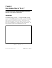
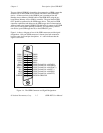
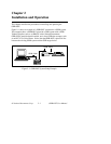
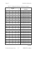
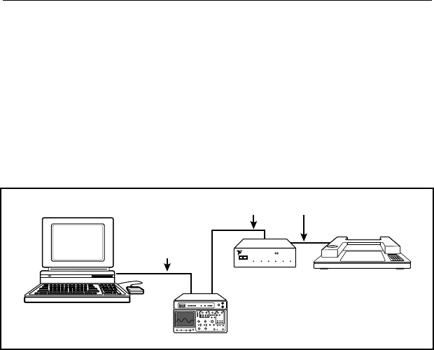
Figure 2-1 shows an example of a GPIB-BUF connected to a GPIB system.
This example shows a GPIB-BUF placed in a GPIB system with a GPIB
Talker/Controller, such as an IBM-PC with a National Instruments
GPIB-PCII Controller board installed, and a slow GPIB data acceptor, such
as an HP 7475A Color Plotter. Notice that the GPIB-BUF is placed in-line
between the existing GPIB system and the GPIB target device.
GPIB Cable
GPIB-BUF
IEEE 488 IEEE 488 BUFFER
POWER READY TALK LISTEN EMPTY FULL
NATIONAL
INSTRUMENTS
®
GPIB Cable
Figure 2-1. GPIB-BUF System Setup Example