


Chapter 2 Introduction to SISO Design
Xmath Interactive Control Design Module 2-2 ni.com
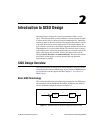
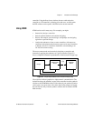
The equations describing this system are as follows:
where y denotes the plant output or sensor signal
u denotes the plant input or actuator signal
r denotes the reference or command input signal
e denotes the error signal
P denotes the plant transfer function
C denotes the controller transfer function
In ICDM, the plant and controller transfer function are required to be
rational, that is, the ratio of two polynomials:
where n
p
, d
p
, n
c
, and d
c
are polynomials called the plant numerator,
plant denominator, controller numerator, and controller denominator,
respectively. The symbols n and d are mnemonics for numerator and
denominator. The degree of d
p
is the plant order or plant degree. Similarly,
the degree of d
c
is the controller order or controller degree.
The poles and zeros of these transfer functions are the zeros (roots) of the
denominator and numerator polynomials, respectively.
In ICDM, P and C are required to be proper polynomials; that is, they have
at least as many poles as zeros. In other words, the degree of n
p
is less than
or equal to the degree of d
p
(which is N) and similarly for n
c
and d
c
. In some
situations, the plant and controller are required to be strictly proper, which
means that there are more poles than zeros.
Other important terms include:
• The loop transfer function L is defined as L = PC. The loop gain is the
magnitude of the loop transfer function.
• The sensitivity transfer function is denoted as S and given by
S =1/(1+PC). The sensitivity transfer function is the transfer function
from the reference input r to the error signal e.
yPu=
uCe=
ery–=
Ps()
n
p
s()
d
p
s()
-----------= Cs()
n
c
s()
d
c
s()
-----------=