


Chapter 7 LQG Synthesis
© National Instruments Corporation 7-7 Xmath Interactive Control Design Module
State-Space Interpretation
In LQG theory, the closed-loop poles consist of n “optimal control
eigenvalues” and n “estimator (Kalman filter) eigenvalues.” For
multivariable systems, the optimal control and the optimal estimator
play different roles in the control system. But in the single-actuator,
single-sensor case, the roles are completely symmetric.
In particular, swapping the parameters ρ and ν yields the same final LQG
controller. This symmetry is broken if you use either output weighting or
integral action, however.
Manipulating the Design Parameters
The design parameters ρ and ν can be changed using the associated sliders
or the variable edit boxes. If you type in a value that is outside the current
slider range, the slider range will automatically adjust. You can change the
ranges for the sliders using the Ranges
window.
The parameters T
int
and a can be manipulated using the sliders or variable
edit boxes provided the associated toggle button is on. If the toggle button
is off, then the slider and variable edit box are insensitive; you cannot drag
the slider handle, and you cannot type into the variable edit box.
When the toggle buttons are turned on again, the parameters are restored to
their previous (or default) values.
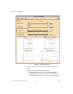
Manipulating the Design Parameters Graphically
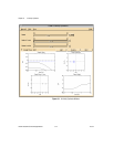
The design parameters also can be manipulated graphically as follows:
• The closed-loop poles are shown on the two symmetric root locus
plots. They can be dragged along the root locus plot, which results
in setting the parameters ρ or ν appropriately.
•When the Decay Rate toggle button is on, a dashed line appears in the
symmetric root locus plots, showing ℜs = a. You can drag this line left
and right to set the Decay Rate parameter.
•When Weight Zero Editing is enabled, the user can graphically
manipulate the zeros of the weight transfer function W on the plot
labeled Weight Poles & Zeros. Refer to the Graphically
Manipulating Poles and Zeros section of Chapter 2, Introduction to
SISO Design, for a general discussion of how to move, add, delete,
or edit these zeros graphically.