


Chapter 8 H-Infinity Synthesis
Xmath Interactive Control Design Module 8-4 ni.com
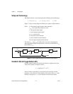
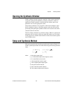
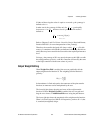
Figure 8-2. Block Diagram Showing the Basic Setup for H-Infinity Synthesis
Figure 8-2 shows a block diagram with the basic setup for H∞ synthesis
where closed-loop transfer matrix H relates the two exogenous inputs w
1
and w
2
to the two outputs z
1
and z
2
.
The design is based on H, the closed-loop transfer matrix relating the noises
w
1
and w
2
to the signals z
1
and z
2
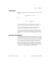
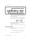
. H is given by the following equation:
The entries of the closed-loop transfer matrix can be interpreted as the
(normalized) transfer functions from the process and sensor noises to
the actuator and output, respectively.
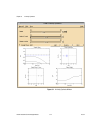
The singular values of H are shown in the top left plot of the H∞ Synthesis
window.
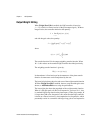
Central H-Infinity Controller
The controller C is chosen to minimize the γ-entropy of the closed-loop
transfer matrix H, given by:
where σ
1
and σ
2
are the singular values of H(jω).
P(s)
r=0
W(s)
y
C(s)
u
w
1
w
2
z
1
z
2
H
1
1 PC+
-----------------
ρPC– ρυC–
PW νPCW–
=
I
γ
H()
γ
2
π
----
1
1 σ
1
ω()γ⁄()
2
–
------------------------------------
1
1 σ
2
ω()γ⁄()
2
–
------------------------------------log+log
⎝⎠
⎜⎟
⎛⎞
dω
0
∞
∫
=