


Chapter 10 Alternate Plant Window
Xmath Interactive Control Design Module 10-2 ni.com
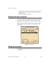
Alternate Plant Window Anatomy
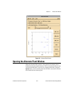
The Alternate Plant window is shown in Figure 10-1. From top to bottom,
it consists of:
• A menu bar with Special, Edit, and View menus.
• A toggle button for controlling whether the plots in ICDM main will
include the response with the alternate plant.
• A toggle button that is used to display the plant poles and zeros in the
plot (refer to Figure 10-1).
• Two toggle buttons that select DC or high frequency normalization
(refer to Figure 10-1).
• A slider and variable edit box for the gain of the alternate plant. These
controls are used to show and also to change the gain of the alternate
plant.
• (Bottom left) A plot for displaying and manipulating the poles and
zeros of the alternate plant. Optionally, the poles and zeros of plant
can be shown.
• (Bottom right) Buttons to Add/Delete/Edit poles and/or zeros of the
alternate plant.