


©
National Instruments Corporation 3-1 PCI-DIO-96 User Manual
Chapter
3
Signal Connections
This chapter describes how to make input and output signal connections
to your PCI-DIO-96 via the board I/O connector.
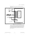
I/O Connector
The I/O connector for the PCI-DIO-96 has 100 pins that you can
connect to 50-pin accessories with the R1005050 cable.
Warning: Connections that exceed any of the maximum ratings of input or output
signals on the PCI-DIO-96 can damage the PCI-DIO-96 board and your
computer. The description of each signal in this chapter includes
information about maximum input ratings. National Instruments is NOT
liable for any damages resulting from signal connections that exceed these
maximum ratings.
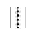
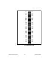
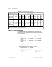
I/O Connector Pin Descriptions
Figures 3-1 and 3-2 show the pin assignments for the PCI-DIO-96
digital I/O connector using the R1005050 ribbon cable.
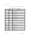
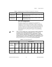
See Table 3-1 for descriptions of each pin on the I/O connector.
!