


Chapter 3 Signal Connections
©
National Instruments Corporation 3-5 PCI-DIO-96 User Manual
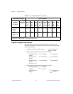
Port C Pin Assignments
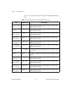
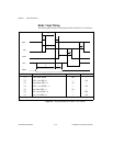
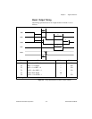
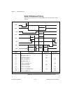
The signals assigned to port C depend on how the 82C55A is
configured. In mode 0, or no handshaking configuration, port C is
configured as two 4-bit I/O ports. In modes 1 and 2, or handshaking
configuration, port C is used for status and handshaking signals with
zero, two, or three lines available for general-purpose I/O. Table 3-2
summarizes the port C signal assignments for each configuration.
Consult Chapter 6, Programming, for register-level programming
information.
Note: Table 3-2 shows both the port C signal assignments and the terminology
correlation between different documentation sources. The 82C55A
terminology refers to the different 82C55A configurations as modes
whereas NI-DAQ, ComponentWorks, LabWindows/CVI, and LabVIEW
documentation refers to them as handshaking and no handshaking. These
signal assignments are the same for all four 82C55A PPIs. Refer to Port
Identification in Chapter 6, Programming, for more information.
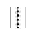
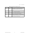
83, 85, 87, 89,
91, 93, 95, 97
CPA<7..0> Bidirectional data lines for port A of PPI C—CPA7 is the
MSB, CPA0 the LSB.
84, 86, 88, 90,
92, 94, 96, 98
DPA<7..0> Bidirectional data lines for port A of PPI D—DPA7 is the
MSB, DPA0 the LSB.
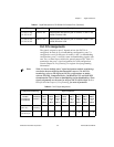
Table 3-2. Port C Signal Assignments
Configuration Terminology Signal Assignments
82C55A/
PCI-DIO-96
User Manual
National
Instruments
Software
APC7,
BPC7,
CPC7,
or
DPC7
APC6,
BPC6,
CPC6,
or
DPC6
APC5,
BPC5,
CPC5,
or
DPC5
APC4,
BPC4,
CPC4,
or
DPC4
APC3,
BPC3,
CPC3,
or
DPC3
APC2,
BPC2,
CPC2,
or
DPC2
APC1,
BPC1,
CPC1,
or
DPC1
APC0,
BPC0,
CPC0,
or
DPC0
Mode 0
(Basic I/O)
No
Handshaking
I/O I/O I/O I/O I/O I/O I/O I/O
Mode 1
(Strobed Input)
Handshaking I/O I/O IBF
A
STB
A
* INTR
A
STB
B
* IBFB
B
INTR
B
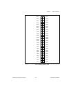
Table 3-1. Signal Descriptions for PCI-DIO-96 I/O Connector Pins (Continued)
Pin Signal Name Description