


Chapter 3 Signal Connections
PCI-DIO-96 User Manual 3-6
©
National Instruments Corporation
Digital I/O Signal Connections
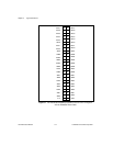
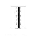
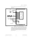
Pins 1 through 48 and pins 51 through 98 of the I/O connector are
digital I/O signal pins. The following specifications and ratings apply
to the digital I/O lines.
• Absolute maximum voltage rating -0.5 to +5.5 V with
respect to GND
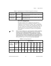
• Digital input specifications (referenced to GND):
• Digital output specifications (referenced to GND):
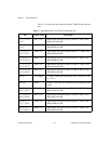
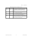
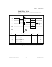
Mode 1
(Strobed
Output)
Handshaking OBF
A
* ACK
A
* I/O I/O INTR
A
ACK
B
* OBF
B
* INTR
B
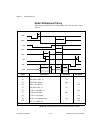
Mode 2
(Bidirectional
Bus)
Handshaking OBF
A
* ACK
A
* IBF
A
STB
A
* INTR
A
I/O I/O I/O
*Indicates that the signal is active low.
Subscripts A and B denote port A or port B handshaking signals.
– Input logic high
voltage
2.2 V minimum 5.3 V maximum
– Input logic low
voltage
-0.3 V minimum 0.8 V maximum
– Maximum input
current
(0 < V
in
< 5 V)
-1 µA minimum 1 µA maximum
– Output logic high
voltage at
3.7 V minimum
I
out
= -2.5 mA
—
– Output logic low
voltage
— 0.4 V maximum at
I
out
= 2.5 mA
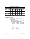
Table 3-2. Port C Signal Assignments (Continued)
Configuration Terminology Signal Assignments
82C55A/
PCI-DIO-96
User Manual
National
Instruments
Software
APC7,
BPC7,
CPC7,
or
DPC7
APC6,
BPC6,
CPC6,
or
DPC6
APC5,
BPC5,
CPC5,
or
DPC5
APC4,
BPC4,
CPC4,
or
DPC4
APC3,
BPC3,
CPC3,
or
DPC3
APC2,
BPC2,
CPC2,
or
DPC2
APC1,
BPC1,
CPC1,
or
DPC1
APC0,
BPC0,
CPC0,
or
DPC0