


Chapter 5 Register Map and Description
©
National Instruments Corporation 5-9 PCI-DIO-96 User Manual
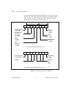
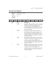
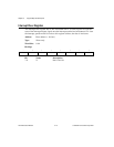
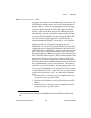
Interrupt Control Register 2
Address: Base address + 15 (hex)
Type: Write-only
Word Size: 8-bit
Bit Map:
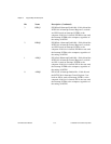
Bit Name Description
7–3 X Don’t care bit.
2 INTEN Interrupt Enable Bit—If this bit is set, the
PCI-DIO-96 can interrupt the computer. If this bit is
cleared, the PCI-DIO-96 cannot generate interrupts
to the computer, regardless of the status of the bits in
Interrupt Control Register 2.
1 CTRIRQ Counter Interrupt Enable Bit—If this bit is set, the
82C53 counter outputs can interrupt the computer. If
this bit is cleared, the counter outputs have no effect.
0 CTR1 Counter Select Bit—If this bit is set, the output from
counter 1 of the 82C53 is connected to the interrupt
request circuitry. In this mode, counter 0 of the
82C53 acts as a frequency scaler for counter 1,
which generates the interrupt. If CTR1 is cleared, the
output from counter 0 of the 82C53 is connected to
the interrupt request circuitry. In this mode,
counter 0 generates the interrupt. For more
information, see the section Interrupt Programming
Example for the 82C53 in Chapter 6, Programming.
7 6 5 4 3 2 1 0
X X X X X INTEN CTRIRQ CTR1