


Chapter 6 Programming
©
National Instruments Corporation 6-19 PCI-DIO-96 User Manual
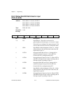
Bit Name Description (Continued)
2-0 I/O Input/Output—Use these bits for general-purpose
I/O lines if group B is configured for mode 0. If
group B is configured for mode 1, refer to the bit
explanations shown in the preceding mode 1
sections.
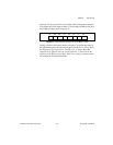
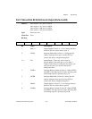
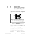
Figure 6-8 shows the port C pin assignments on the digital I/O
connector when port C is configured for mode 2. Notice that the status
of STBA* and the status of ACKA* are not included in the port C status
word.
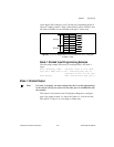
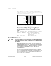
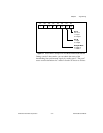
Figure 6-8. Port C Pin Assignments on I/O Connector when Port C is
Configured for Mode 2
Mode 2 Bidirectional Bus Programming Example
The following example shows how to configure PPI A for mode 2 input
and output.
Write (8255Cnfg, 0xC0) Set mode 2 — port A
is bidirectional
Loop until OBFA (PC7) is set, indicating that the
data last written to port A
has been read
Write (PortA, Data) Write data to port A
Loop until IBFA (PC5) is set, indicating that data is
available in port A to be read
Read (PortA) Now, read the data from port A
PC7 OBFA*
PC6 ACKA*
PC5 IBFA
PC4 STBA*
PC3 INTRA
PC2 #
PC1 #
PC0 #
Group A
Group B
# The three port C lines associated with group B function based on the
mode selected for group B; that is, if group B is configured for mode 0,
PC<2..0> function as general-purpose I/O, but if group B is configured
for mode 1 input or output, PC<2..0> function as handshaking lines as
shown in the preceding mode 1 sections.