


Chapter 6 Programming
©
National Instruments Corporation 6-15 PCI-DIO-96 User Manual
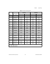
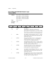
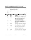
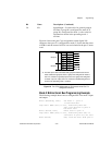
Port C Status-Word Bit Definitions for Output (Ports A and B)
Address: Base address + 03 (hex) for PPI A
Base address + 07 (hex) for PPI B
Base address + 0B (hex) for PPI C
Base address + 0F (hex) for PPI D
Type: Read and write
Word Size: 8-bit
Bit Map:
Bit Name Description
7 OBFA* Output Buffer for Port A—A low setting indicates
that the CPU has written data to port A.
6 INTEA Interrupt Enable Bit for Port A—Setting this bit
enables interrupts from port A of the 82C55A.
Control this bit by setting/resetting PC6.
5–4 I/O Input/Output—These bits can be used for
general-purpose I/O when port A is in mode 1
output. If these bits are configured for output, you
must use the port C bit set/reset function to
manipulate them.
3 INTRA Interrupt Request Status for Port A—When INTEA
and OBFA* are high, this bit is high, indicating that
an interrupt request is pending for port A.
2 INTEB Interrupt Enable Bit for Port B—Setting this bit
enables interrupts from port B of the 82C55A.
Control this bit by setting/resetting PC2.
1 OBFB* Output Buffer for Port B—A low setting indicates
that the CPU has written data to port B.
0 INTRB Interrupt Request Status for Port B—When INTEB
and OBFB* are high, this bit is high, indicating that
an interrupt request is pending for port B.
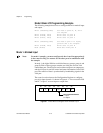
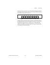
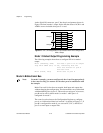
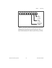
7 6 5 4 3 2 1 0
OBFA* INTEA I/O I/O INTRA INTEB OBFB* INTRB