Chapter 4 Debugging Your Application
© National Instruments Corp. 4-3 NI-488.2 User Manual for Windows
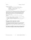
Hardware Information:
GPIB0: an AT-GPIB/TNT board using the TNT4882C chip.
It supports both the NI-488 functions and NI-488.2
routines.
It supports the HS488 high-speed protocol.
It uses base I/O address 0x2C0.
It uses interrupt level 11.
It uses DMA channel 5.
You can also run GPIBInfo by specifying the base I/O address of a GPIB board in your
system. If GPIBInfo finds a board at the given address, it displays information about
that board. This feature of GPIBInfo is useful in determining whether you have a
GPIB board installed at a particular address. If you have a board installed at base I/O
address 2C0 (hex), entering gpibinfo 0x2c0 produces the following output:
GPIBInfo (Sep 29 1993)
Copyright (c) 1993 National Instruments Corp. All rights
reserved.
The board at base I/O address 0x2C0 appears to be an AT-GPIB/TNT.
It uses the TNT4882C GPIB Controller chip.
It supports both the NI-488 functions and the NI-488.2 routines.
It supports the HS488 high-speed protocol.
The NI-488.2 software is configured to access this board as
GPIB0.
Debugging with the Global Status Variables
After each function call to your NI-488.2 driver, ibsta, iberr, ibcnt , and ibcntl
are updated before the call returns to your application. You should check for an error
after each GPIB call. Refer to Chapter 3, Developing Your Application, for more
information about how to use these variables within your program to automatically check
for errors.
After you determine which GPIB call is failing and note the corresponding values of the
global variables, refer to Appendix A, Status Word Conditions, and Appendix B, Error
Codes and Solutions. These appendixes will help you interpret the state of the driver.


