© National Instruments Corporation 11 NI 4070/4072 Calibration Procedure
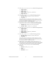
27. Call niDMM_ConfigureMultiPoint with the following parameters:
• Trigger Count =
1
• Sample Count = 10
• Sample Trigger = NIDMM_VAL_IMMEDIATE
• Sample Interval = –1
28. Call niDMM_ReadMultiPoint with the following parameters:
• Maximum Time =
NIDMM_VAL_TIME_LIMIT_AUTO
• Array Size = 10
Average the results by summing the returned reading array of the
function and dividing by the returned actual number of points. Store
the result as the 100 mV >10 GΩ mode offset.
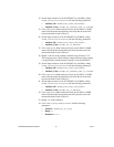
29. Set the input resistance of the NI 4070/4072 to 10 MΩ by calling
niDMM_SetAttributeViReal64 with the following parameters:
• Attribute_ID =
NIDMM_ATTR_INPUT_RESISTANCE
• Attribute_Value = NIDMM_VAL_10_MEGAOHM
30. Call niDMM_ConfigureMultiPoint with the following parameters:
• Trigger Count =
1
• Sample Count = 10
• Sample Trigger = NIDMM_VAL_IMMEDIATE
• SampleInterval = –1
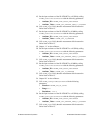
31. Call niDMM_ReadMultiPoint with the following parameters:
• Maximum Time =
NIDMM_VAL_TIME_LIMIT_AUTO
• Array Size = 10
Average the results by summing the returned reading array of the
function and dividing by the returned actual number of points. Store
the result as the 100 mV 10 MΩ mode offset.
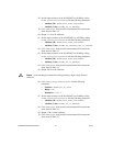
32. Output 100 mV on the calibrator with the range locked to 2.2 V.
This range prevents a 50 Ω calibrator output resistance from creating
a voltage divider with the internal resistance of the NI 4070/4072.
33. Call
niDMM_ConfigureMeasurement with the following
parameters:
• Function =
NIDMM_VAL_DC_VOLTS
• Range = 0.1
• Resolution = 100e–9


