Chapter 1 Generating Functions with the NI 5401
NI 5401 User Manual 1-6 www.natinst.com
Signal Descriptions
Table 1-1 shows the pin names and signal descriptions used on the NI 5401
digital output connector.
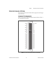
SHC50-68 50-Pin Cable Connector
You can use an optional SHC50-68 50-pin to 68-pin cable for external
trigger input. The cable connects to the digital connector on the NI 5401.
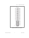
Figure 1-5 shows the 68-pin connector pin assignments on the SHC50-68
cable.
Note
The SHC50-68 connector uses the same signals as the NI 5401 digital output
connector shown in Table 1-1.
Table 1-1.
Digital Connector Signal Descriptions
Signal Name Type Description
DGND – Digital ground
EXT_TRIG Input External trigger—The external trigger input signal is a
TTL-level signal that you can use to start or step through a
waveform generation. For more information on trigger sources
and trigger mode, see Chapter 2, Function Generator
Operation.
NC – Not connected.
RFU – Reserved for future use. Do not connect signals to this pin.


