Chapter 2 Function Generator Operation
NI 5401 User Manual 2-8 www.natinst.com
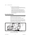
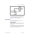
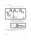
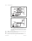
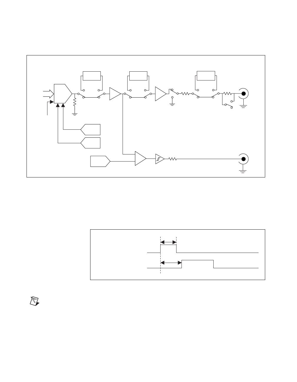
Figure 2-8 shows the essential block diagram of analog waveform
generation.
Figure 2-8. Analog Output and SYNC Out Block Diagram
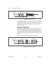
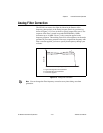
Figure 2-9 shows the timing relationships of the trigger input and
waveform output. T
d1
is the pulse width on the trigger signal. T
d2
is the time
delay from trigger to output on Arb output. Refer to Appendix A,
Specifications, for more information on these timing parameters.
Figure 2-9. Waveform and Trigger Timings
Note
You can switch off the analog lowpass filter at any time during waveform generation.
When you change this setting, the bouncing of electromechanical relays on the NI 5401
distorts the output signal for about 10 ms.
DAC
Gain
DAC
Pre Amp
Main Amp
Filter
Lowpass
10 dB
Attenuator
Attenuators
Output
Enable
25 Ω
Arb
Selector
50 Ω/75 Ω
Offset
DAC
12
Clock
Level
DAC
+
-
SYNC
Comparator
50 Ω
50 Ω
(63 dB in 1 dB steps)
Trigger Input Signal
(Slope: Positive, TTL)
Waveform Output
(±5 V
pp
into 50 Ω
)
T
d1
T
d2


