Appendix A Specifications
NI 5401 User Manual A-2 www.natinst.com
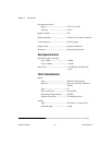
Pre-attenuation offset
Range...............................................±2.5 V into 50 Ω
1
Accuracy..........................................±5 mV
Output coupling .....................................DC
Output impedance ..................................50 Ω or 75 Ω software selectable
Load impedance .....................................50 Ω or greater
Output enable..........................................Software switchable
Protection................................................Short-circuit protected
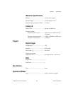
Sine Spectral Purity
Harmonic products and spurs
Up to 1 MHz....................................–60 dBc
Up to 16 MHz..................................–35 dBc
Phase noise .............................................–105 dBc/Hz at 10 kHz from
carrier
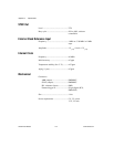
Filter Characteristics
Digital
Type.................................................Half-band interpolating
Selection ..........................................Software switchable (enable or
disable)
Taps ................................................67
Filter coefficients ............................Fixed 20-bit
Data interpolating frequency ..........80 MS/s
Pipeline signal delay .......................26 sampling periods
Analog
Type.................................................7th-order L-C lowpass filter
Passband ripple................................±2 dB
1
With less than 10 dB of attenuation, signal maximum plus offset (before attenuation) must not exceed ±5 V (into 50
Ω)


