


Appendix C Cabling Requirements for PXI-8460 Low-Speed CAN
PXI-8461 or PXI-8460 and NI-CAN for Windows 98/95 C-6 www.natinst.com
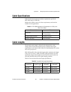
values of 510 Ω ±5% per port. The PXI-8460 kit also includes a pair of
15 kΩ ±5% resistors for each port. After determining the termination of
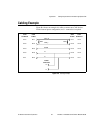
your existing network or device, you can use the following formula to
indicate which value should be placed on your PXI-8460 board in order to
produce the proper overall RTH and RTL termination of 100 to 500 Ω upon
connection of the board:
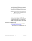
*R
RTH overall
should be between 100 and 500 Ω
**R
RTH of low-speed CAN interface
= 510 Ω ±5% (mounted) or 15 kΩ ±5% (in kit)
†R
RTH
= R
RTL
As the formula indicates, the 510 Ω ±5% shipped on your board will work
with properly terminated networks having a total RTH and RTL
termination of 125 to 500 Ω, or individual devices having an RTH and RTL
termination of 500 Ω to 16 kΩ. For communication with a network having
an overall RTH and RTL termination of 100 to 125 Ω, you will need to
replace the 510 Ω resistors with the 15 kΩ resistors in the kit. Please refer
to the next section, Replacing the Termination Resistors.
Replacing the Termination Resistors
Follow these steps to replace the termination resistors, after you have
determined the correct value in the previous section, Determining the
Necessary Termination Resistance for Your Board.
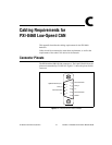
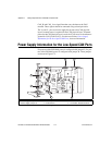
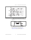
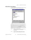
1. Remove the termination resistors on your PXI-8460. Figure C-5 shows
the location of the termination resistor sockets on a PXI-8460.
R
RTH overall*
†
1
1
R
RTH of low-speed CAN interface**
-----------------------------------------------------------------
1
R
RTH of existing network or device
--------------------------------------------------------------+
-------------------------------------------------------------------------------------------------------------------------------------------=