


Contents
© National Instruments Corporation vii PXI-8461 or PXI-8460 and NI-CAN for Windows 98/95
Appendix F
Technical Support Resources
Glossary
Figures
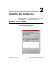
Figure 2-1. Add/Remove Programs Properties Dialog Box.....................................2-1
Figure 2-2. Installing the PXI Hardware..................................................................2-3
Figure 2-3. Device Manager Shows PXI-8461 That Is Working Properly..............2-4
Figure 2-4. Device Manager Shows PXI-8461 That Is Not Working Properly.......2-5
Figure 2-5. NI-CAN Hardware Settings Dialog Box...............................................2-5
Figure 3-1. NI-CAN Diagnostic Utility after Testing..............................................3-1
Figure A-1. Selecting an Interface to Remove from Windows 98/95 ......................A-2
Figure A-2. Add/Remove Programs Properties Dialog Box.....................................A-3
Figure B-1. Pinout for 9-Pin D-Sub Connector........................................................B-1
Figure B-2. Pinout for 5-Pin Combicon-Style Pluggable Screw Terminal ..............B-2
Figure B-3. PXI-8461 Parts Locator Diagram..........................................................B-3
Figure B-4. Power Source Jumpers ..........................................................................B-4
Figure B-5. Termination Resistor Placement ...........................................................B-6
Figure B-6. Cabling Example...................................................................................B-7
Figure C-1. Pinout for 9-Pin D-Sub Connector........................................................C-1
Figure C-2. PXI-8460 Parts Locator Diagram..........................................................C-2
Figure C-3. Power Source Jumpers ..........................................................................C-3
Figure C-4. Termination Resistor Placement for Low-Speed CAN.........................C-5
Figure C-5. Location of Termination Resistors on a PXI-8460 ...............................C-7
Figure C-6. Preparing Lead Wires of Replacement Resistors..................................C-7
Figure C-7. Cabling Example...................................................................................C-8
Figure D-1. Device Manager Shows PXI-8461 That Is Not Working Properly.......D-3
Tables
Table B-1. Power Requirements for the CAN Physical Layer for
Bus-Powered Versions..........................................................................B-4
Table B-2. ISO 11898 Specifications for Characteristics of a CAN_H and
CAN_L Pair of Wires............................................................................B-5
Table B-3. DeviceNet Cable Length Specifications................................................B-5