


Windows Setup and Operation 3-17
PCI module 2: PCI module (for Group2)
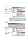
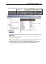
[Left pane]
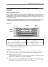
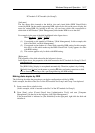
The tree shows disks inserted to the built-in slots and virtual disks (RDR Virtual Disks)
created by RDR. On the models supporting RDR, right-click a disk on the tree to display the
menu for setting RDR. By looking at the tree, you can know which disk corresponds to
which disk of the Windows’ [Disk Management] and whether RDR is set to the disk.
For example, in the case of the disk highlighted in the figure above:
Disk (
Harddisk1LUN2PLEX1)
(1) (2) (3)
(1) Corresponds to the number of Windows’ [Disk Management]. In this example, this
disk is the Disk1 on [Disk Management].
(2) Corresponds to the number of a virtual disk created by RDR setting. In this example,
this disk is a disk which makes up the RDR Virtual Disk 2 (only appears for disks
with RDR setting).
(3) This section appears only for disks with RDR setting.
[Right pane]
The properties of the disk selected in the left pane is shown.
In the figure above, the properties of the disk inserted to the PCI module for Group1’s Slot 2.
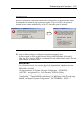
IMPORTANT:
The [RDR Utility] display is not updated automatically. Therefore, update it by clicking
[Refresh] from [Action] on the menu or pressing F5 after performing operations to disk
such as inserting/removing a disk, specifying/removing the RDR setting.
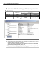
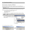
Making disks duplex by RDR
The following describes the procedure to set duplex configuration to disks by RDR.
In this example, the disks of the Slot 2 of the PCI modules for Group1 and Group 2 are duplexed.
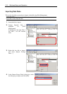
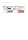
1. Insert a new disk to a built-in slot.
(In this example, a disk is inserted to the Slot 2 of the PCI module for Group1.)
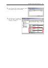
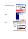
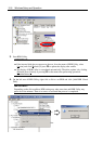
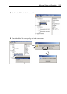
2. From [Start], select [Control Panel] then [Administrative Tools] and start [Computer
Management]. On the tree in the left pane, click [Disk Management].
If the inserted disk is indicated as [Not Initialized] in the right pane, right-click the disk and
initialize it.