


CHAPTER 1 OVERVIEW
User’s Manual U15776EJ1V0UM
12
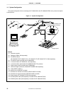
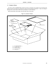
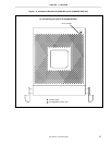
1.4 System Configuration
The system configuration when connecting the IE-703002-MC to the IE-703089-MC-EM1 and a personal computer
is shown below.
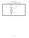
Figure 1-1. System Configuration
[Magnified drawing: Example of use
of connector for target connection]
Target
system
<13>
<14>
<12>
<5>
<6>
<7>
<4>
<3>
<1>, <2>
<9>
<11>
Target system
<10>
<11>
<8>
<15>
<12>
Remark
<1> Personal computer
<2> Debugger (ID850: Sold separately)
<3> PC interface board
(IE-70000-98-IF-C/IE-70000-PC-IF-C, IE-70000-PCI-IF-A/IE-70000-CD-IF-A: Sold separately)
<4> PC interface cable (included with IE-703002-MC)
<5> In-circuit emulator (IE-703002-MC: Sold separately)
<6> In-circuit emulator option board (IE-703089-MC-EM1: This product)
<7> External logic probe (included with IE-703002-MC)
<8> Socket for target connection (YQSOCKET144SDN: Sold separately)
<9> Probe (SWEX-144SD-1)
<10> Guide screw (YQGUIDE: Included)
<11> Connector for emulator connection (YQPACK144SD: Included)
<12> Connector for target connection (NQPACK144SD: Included)
<13> Power adapter (IE-70000-MC-PS-B: Sold separately)
<14> AC100V power cable (sold separately: Included with IE-70000-MC-PS-B)
<15> AC220V power cable (sold separately: Included with IE-70000-MC-PS-B)