


CHAPTER 1 OVERVIEW
User’s Manual U15776EJ1V0UM
15
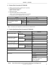
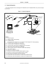
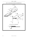
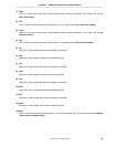
1.6 Connection Between IE-703002-MC and IE-703089-MC-EM1
The procedure for connecting the IE-703002-MC and IE-703089-MC-EM1 is described below.
Caution Connect carefully so as not to break or bend connector pins.
<1> Remove the pod cover (lower) of the IE-703002-MC.
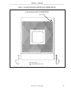
<2> Set the PGA socket lever of the IE-703089-MC-EM1 to the OPEN position as shown in Figure 1-4 (b).
<3> Connect the IE-703089-MC-EM1 to the PGA socket at the back of the IE-703002-MC pod (refer to Figure 1-4
(c)). When connecting, position the IE-703002-MC and IE-703089-MC-EM1 so that they are horizontal.
<4> Set the PGA socket lever of the IE-703089-MC-EM1 to the CLOSE position as shown in Figure 1-4 (b).
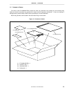
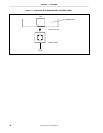
<5> When connecting the probe (SWEX-144SD-1) to the IE-703089-MC-EM1, attach it to CN1 on the rear of the
IE-703089-MC-EM1, aligning each pin 1 (refer to Figure 1-5).
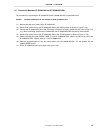
<6> Place the supplied spacers in the four corner holes of the IE-703089-MC-EM1. Fix the spacers with the
supplied SEMS screws.
<7> Fix the IE-703002-MC pod cover (upper) with nylon rivets.