


User’s Manual U15776EJ1V0UM
30
CHAPTER 5 DIFFERENCES BETWEEN TARGET DEVICE AND TARGET INTERFACE CIRCUIT
Differences between the signal lines of the target device and the signal lines of the IE-703089-MC-EM1 target
interface circuit are described in this chapter.
The target device is a CMOS circuit, whereas the target interface circuit of the IE-703089-MC-EM1 is configured
with an emulation circuit such as a gate array TTL or CMOS-IC.
When debugging the IE system connected to the target system, the IE system emulates as if the real target device
is operating on the target system.
Small differences occur however, because the IE system is emulating actual operation.
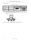
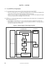
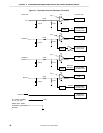
(1) Signals input/output to/from the emulation gate array
• P47 to P40
• P57 to P50
• P67 to P60
• P97 to P90
• P117 to P110
• P133 to P130
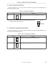
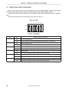
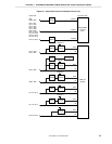
(2) Other signals
• P07 to P00
• P17 to P10
• P27 to P20
• P37 to P30
• P77 to P70
• P83 to P80
• P107 to P100
• P127 to P120
• P147 to P140
• P157 to P150
• P176 to P170
• V
DD0
• PORTVDD0
, PORTV
DD1
, PORTV
DD2
, ADCV
DD
• CLKOUT
• RESET
• VDD1
• MODE/VPP
• CPUREG
• X1, X2, XT1, XT2
• GND0, GND1, GND2, PORTGND0, PORTGND1, ADCGND
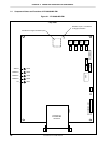
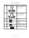
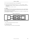
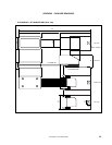
Figure 5-1 shows the signals in (1) and (2) above in the circuit for the IE system.