


CHAPTER 2 NAMES AND FUNCTIONS OF COMPONENTS
User’s Manual U15776EJ1V0UM
23
2.2 Clock Settings
This section describes the clock settings.
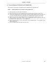
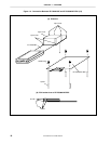
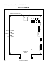
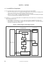
For the position of OSC1 and JP5 in the IE-703089-MC-EM1, refer to Figure 2-1.
For the jumper and switch positions in the IE-703002-MC, refer to the IE-703002-MC User’s Manual (U11595E).
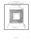
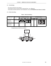
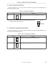
2.2.1 Main clock setting
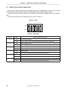
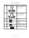
Table 2-1. Main Clock Setting
IE-703089-MC-EM1 Setting IE-703002-MC SettingEmulator Usage
Environment
Clock Supply
Method
OSC1 JP5 SW1 SW2 JP2
When using
emulator as
standalone unit
Internal clock
When using
emulator with
target system
Internal clock
17
(Oscillator mounted)
7
8
1
2
(3-4 shorted: Fixed)
ON OFF
1
7
8
2
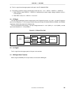
Caution Emulation cannot be performed by inputting a clock from the target system.
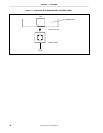
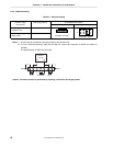
The specifications of OSC1 are as follows.
GND
1 MΩ
GND
V850/SCx
I/O
chip
X1
X2
1
10 pF 20 MHz
7
10 pF