


User’s Manual U15776EJ1V0UM
27
CHAPTER 3 FACTORY SETTINGS
Item Description Remark
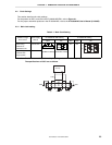
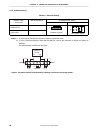
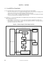
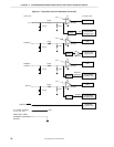
OSC1
GND
1 MΩ
GND
V850/SCx
I/O chip
X1 X2
1
10 pF 20 MHz
7
10 pF
Pins 1 and 2: For mounting capacitor (10 pF)
Pins 6 and 7: For mounting capacitor (10 pF)
Pins 3 to 5: Crystal oscillator (20 MHz)
Pin 4: Open
20 MHz clock supplied for main clock
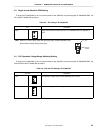
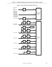
OSC2
GND
GND
V850/SCx
I/O chip
XT2 XT1
1
27 pF 32.768 kHz
7
27 pF
Pins 1 and 2: For mounting capacitor (27 pF)
Pins 6 and 7: For mounting capacitor (27 pF)
Pins 3 to 5: Crystal oscillator (32.768 MHz)
Pin 4: Open
32.768 MHz clock supplied for subclock
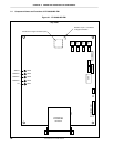
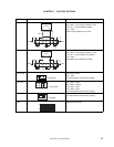
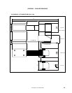
JP1 to JP4
123
(2-3 shorted)
Pins 2 and 3: Short
Pin 1: Open
Use these jumpers with the factory settings.
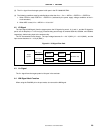
JP5, JP6
1
2
7
8
(3-4 shorted)
Pins 1 and 2: Open
Pins 3 and 4: Shorted
Pins 5 and 6: Open
Pins 7 and 8: Open
Use these jumpers with the factory settings.
SW1 to SW4
1
6
3
4
(3-6 side)
3-6 side
Use these switches with the factory settings.
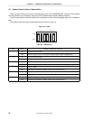
SW5
163425
ON
OFF
All bits ON (port mode)