


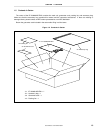
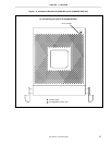


CHAPTER 2 NAMES AND FUNCTIONS OF COMPONENTS
User’s Manual U15776EJ1V0UM
21
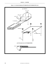
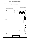
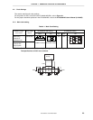
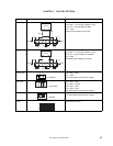
(1) OSC1
OSC1 is a socket for the main clock crystal oscillator and for mounting capacitors. (For details, refer to 2.2.1
Main clock setting).
(2) JP5
JP5 is a jumper to switch the main clock supply source. (For details, refer to 2.2.1 Main clock setting.)
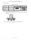
(3) OSC2
OSC2 is a socket for the main clock crystal oscillator and for mounting capacitors. (For details, refer to 2.2.2
Subclock setting.)
(4) JP6
JP6 is a jumper to switch the subclock supply source. (For details, refer to 2.2.2 Subclock setting.)
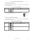
(5) JP1
Reserved. Use this jumper with the factory setting (2-3 shorted).
(6) SW1
Reserved. Use this switch with the factory setting (3-6 side).
(7) JP2
Reserved. Use this jumper with the factory setting (2-3 shorted).
(8) SW2
Reserved. Use this switch with the factory setting (3-6 side).
(9) JP3
Reserved. Use this jumper with the factory setting (2-3 shorted).
(10) SW3
Reserved. Use this switch with the factory setting (3-6 side).
(11) JP4
Reserved. Use this jumper with the factory setting (2-3 shorted).
(12) SW4
Reserved. Use this switch with the factory setting (3-6 side).
(13) SW5
SW5 is a switch to output the addresses (A1 to A15) of the separate bus. (For details, refer to 2.5 Address
Output Setting of Separate Bus.)