


6
1. Introduction
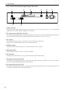
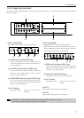
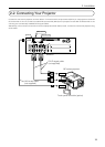
1-3-4. Control Terminals/Image Output Terminals
12345
6
7
8
1. LAN port (RJ-45)
This port is used for linked control from the NC series projector or for control of this unit from a PC. Use a commercially
available LAN cross cable 10Base-T/100Base-T) for connection.
2. PC control terminal (RS-232C, D-Sub 9P)
This is a terminal for system extension. It is used to operate this unit by exclusive command via RS-232C interface with a PC.
Use a commercially available RS-232C straight cable (male-female cable) to connect this unit to a PC.
3. PC card slot
Set a wireless LAN card, and you can control this unit from a PC using a wireless LAN.
Please inquire your dealer/distributor about use of a wireless LAN card.
4. USB port (type A)
This terminal is for the service personnel. It is used for maintenance of the switcher.
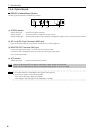
5. Main power switch
Set the main power switch to “| (ON)” to have the unit standby.
6. AC IN terminal
Connect the AC IN terminal of this unit in the wall outlet using the attached power cable.
7. DVI output A terminal (DVI-D 24P)
This terminal is for high 8-bit output of DVI. Connect this terminal with the DVI-A input terminal on the NC series projector.
Use a commercially available DVI-D signal cable (single link).
8. DVI output B terminal (DVI-D 24P)
This terminal is for low 2-bit output of DVI. Connect this terminal with the DVI-B input terminal on the NC series projector. Use
a commercially available DVI-D signal cable (single link).