


7
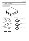
1. Introduction
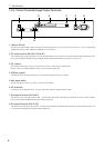
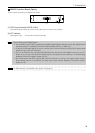
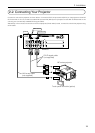
1-3-5. Image Input terminals
You can mount various interface boards to any position you want among slots 1 to 4. For removal and installation of the interface
board, see page 13.
1
2
3
4
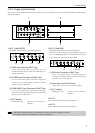
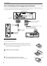
1.SLOT 1 (MM-VIDEO)
MM-VIDEO interface board is standard equipment.
(1) (2) (3) (4)
(1) CVBS Input Connector (BNC Type)
Use a 75 Ω coaxial cable and connect it to the
Composite Video output connector of a DVD player, or
to other equipment.
(2) S-VIDEO Input Connectors (2 BNC Type)
Use a 75 Ω coaxial cable (2-conductor type) and
connect it to the S-Video output connector of a DVD
player, or to other equipment.
(3) COMPONENT Input Connectors (3 BNC Type)
Use a 75 Ω coaxial cable (3-conductor type) and
connect it to the Component output connector of a DVD
player, or to other equipment.
(4) ACT Indicator
Steady green light ........ Shows that this board is
selected.
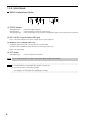
2.SLOT 2 (MM-RGB)
MM-RGB interface board is standard equipment.
Make sure to mount the accessory ferrite clamp core to the
end of the RGB signal cable. The ferrite clamp core should
be mounted as close to this unit as possible.
(1) (2) (3)
(1) RGB Input Connectors (5 BNC Type)
Use a 75 Ω coaxial cable (5-conductor type) and
connect it to the display output connector of a personal
computer or to other equipment.
(2) Audio Input Jacks (RCA-Phono)
These Jacks have no function with the Switcher.
(3) ACT Indicator
Steady green light ........ Shows that this board is
selected.
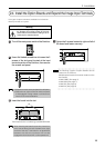
3.SLOT 3
Use to extend the input terminal. See page 13.
4.SLOT 4
Use to extend the input terminal. See page 13.
NOTE
• MM-VIDEO interface board and MM-RGB interface board are available as an option.
• For details about the available input signals, see page 23.