


8
1. Introduction
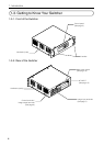
1-3-6. Option Boards
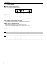
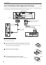
MM-SDI Interface Board (Option)
The SDI signal input board is available as an option.
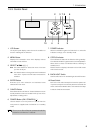
(1) (2) (3) (4)
(1) STATUS Indicator
Steady green light ....... Shows that a signal is present.
Steady red light ........... Shows that there is no signal or an error occurs.
Steady orange light ..... Show that abnormality of input interface is displayed. Do again to turn on the power of the switcher.
(2) SDI 1 and SDI 2 Input Connectors (BNC type)
Use a 75 Ω coaxial cable and connect it to a video server or video equipment.
(3) MONITOR OUT Connector (BNC type)
Outputs the signal from the SDI 1 or SDI 2 input you currently select.
Connect this with a dedicated monitor and use it for checking the input signal.
Use a 75 Ω coaxial cable.
(4) ACT Indicator
Steady green light ....... Shows that this board is selected.
NOTE
Use the 75 Ω coaxial (5C-2V) cable or equivalent. Higher quality recommended.
Using a thinner cable than the above can degrade image quality or cause no image.
TIP
• For details about the compatible input signals, see page 23.
• Cycle the unit power in the following cases.
• The status indicator is lighting in orange.
• The image of the SDI signal is not displayed in normally.