


13
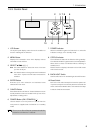
2. Installation
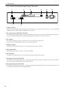
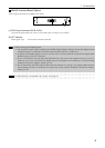
2-4. Install the Option Boards and Expand the Image Input Terminals
Four types of option boards are available for the Switcher.
Please purchase as required.
Warning
When installing or removing the board from
the Switcher, do so after turning off the main
power switch of the Switcher. Failing to do so
could result in electrical shock.
1
Turn off the main power switch of the Switcher.
2
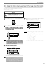
Use a flat-bladed screwdriver to loosen the 2
screws of the slot panel located at the input
terminals portion of the Switcher, then remove
the screws and panel.
NOTE
• Keep the removed screws and panel in a safe place.
• Please do not use the Switcher while the panel
is disengaged. Foreign matter could enter the
interior and cause breakdown.
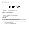
3
Insert the board into the slot.
rail
The example shown in the drawing is the MM-SDI board.
NOTE
When inserting the board into the slot, insert it so
that it moves along the rails located at the right
and left of the slot. If the board is not positioned
between the rails the connector will not be
engaged and the board will not be operational.
4
Tighten the 2 screws located at right and left of
the board and fasten securely.
TIP
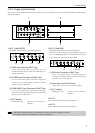
The following 4 types of option boards can be
inserted in the Switcher.
Multiple option boards of the same model can also
be inserted.
• MM-VIDEO (See page 7)
• MM-RGB (See page 7)
• MM-SDI (See page 8)
• MM-DVI (See page 9)