


24
6. Appendix
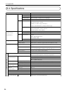
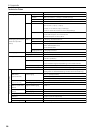
6-4. Specifications
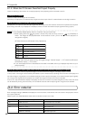
Model Number
Image Input
Image Input
(Optional board
specifications)
Image output
Image signal processing
Input Slot
MM-VIDEO
(Standard board)
MM-RGB
(Standard board)
MM-DVI
(Option board)
MM-SDI
(Option board)
Output Terminal
USB Port
LAN Port
PC Control Terminal
MM2000
BNC x 1, 75 Ω, 1.0 Vp-p
BNC x 2, 75 Ω, Y: 1.0 Vp-p C: 0.28 to 0.3 Vp-p
BNC x 3, 75 Ω, Y: 1.0 Vp-p Cb, Cr: ±0.35 Vp-p
NTSC, PAL: 500 TV SECAM: 300 TV
BNC x 5
G/Y: 75 Ω, 0.7 Vp-p / 1.0 Vp-p
R, B/Cb, Cr: 75 Ω, 0.7 Vp-p / ±0.35 Vp-p
H/CS, V:1 kΩ TTL•75 Ω 0.7 to 2.0Vp-p Selection Type
Maximum sampling frequency: 165 MHz
Horizontal frequency: 31 kHz to 105 kHz
Vertical frequency: 24 Hz to 96 Hz
1 input, dual link supported
Maximum pixel clock frequency: 220 MHz
2 input
SDTV: SMPTE 259M Level-C
HDTV:SMPTE 292M
1 output for monitoring
2048 x 1080 p
DVI-D twin link DVI OUT-A: upper 8-bits, DVI OUT-B: lower 2-bits
10 bits for all processes for each color (excluding RGB, and DVI input
board)
Multi-directional filter method (SDTV, HDTV)
3:2, 2:2 pull down signal, animation format compatible type
Per-pixel motion adaptive method (SDTV)
Multi-directional filter method, Contrast Enhancement
4 slots (One board each for the VIDEO board and analog RGB input
board are standard equipment; 2 slots are for expansion.)
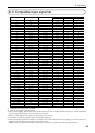
BNC x 1 (Composite Video)
BNC x 2 (S-Video)
BNC x 3 (DVD Component)
BNC x 5 (shared with the component input connectors)
RCA (L/MONO, R) x 1 (No function)
DVI-D x 1
Stereo Mini Jack 1 (No function)
BNC x 2
BNC x 1
DVI-D x 2 (DVI OUT-A, DVI OUT-B)
A Type x1 (For service personnel)
RJ-45 x 1
D-Sub 9 pin x 1 (For service personnel)
VIDEO
RGB
DVI-D
SDI
Resolution
Output method
Color Bit Depth
I/P conversion
Noise reduction
Enhancer
Video Input
Analog RGB Input
Audio Input
Digital RGB Input
Audio Input
SDI Input
SDI Output
IN
Composite Video
S-Video
Component
Video
Horizontal Resolution
R.G.B.H.V.
Frequency
DVI-D connector
Frequency
Input terminal
Output terminal
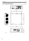
Input / Output Terminals