


48
*** Condential - DO NOT Distribute ***
Director
Filter parameters
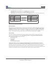
Switches and lters are dened using the lteraddandlterinscommands. The lteradd command syntax is:
lter add in_ports=<portlist> <lter_parameter_list> action=<redir|drop> redir_ports=<portlist>
The <lter_parameter_list> is a sequence of zero or more of the lter qualiers as listed in the following table.
If the <lter_parameter_list> is empty, the lteradd command species an aggregation of the trafc received on all of
the in_ports. If the action=redir, the aggregated trafc stream is regenerated to all of the redir_ports.
If the <lter_parameter_list> contains lters, aggregation and regeneration take place as described in the previous
paragraph. However, the lters are applied to the aggregated trafc stream before it is copied to the Monitor ports. If
multiple lter qualiers are specied, a packet must satisfy all of the lter qualiers in order to be copied to the Moni-
tor ports. In other words, the lter qualiers are combined with a logical AND condition. A logical OR condition can be
created by using multiple lteraddcommands with identical port lists.
The lteraddandlterinscommands dene lters but do not activate them. A subsequent ltercommit or commit
command must be executed to the lters. This mechanism enables an interrelated group of lters to be activated simul-
taneously. It also allows you to double-check your lter denitions before you activate them.
It is important to note that packets are ltered using a Content Addressable Memory or CAM. Each lter is a CAM
entry, and the CAM is lled in the order that the lteraddcommands are received. Filter ins commands create lters
in specic locations in the CAM. When a packet is processed, the rst lter in the CAM that matches the packet is the
only lter that is activated. Each packet can activate exactly zero or one lters. See Understandlterinteractions
near the end of Chapter 3 for examples.
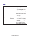
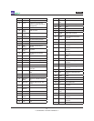
All supported lter qualiers are shown in the following table.
Director Filter Parameters
<qual> <value> Example Description
ip_src IPv4 address ip_src=168.10.4.1 IP source address
ip_src_mask IPv4 address mask ip_src_mask=255.255.255.0 Mask for IP source address
ip_dst IPv4 address ip_dst=1234:5678::9abc IP destination address
ip_dst_mask IPv4 address mask ip_dst_mask=255.255.255.0 Mask for IP destination address
ip_proto Number* ip_proto=6 Layer 4 IP protocol
l4_src_port Port number l4_src_port=80 Layer 4 source port
l4_dst_port Port number l4_dst_port=80 Layer 4 destination port
vlan VLAN number vlan=128 VLAN
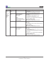
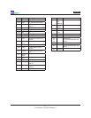
* See Appendix C for a complete list of protocol numbers. Some common protocols include:
Number Keyword Protocol
1 ICMP Internet Control Message Protocol
2 IGMP Internet Group Message Protocol
6 TCP Transmission Control Protocol
17 UDP User Datagram Protocol
89 OSPF Open Shortest Path First
132 SCTP Stream Control Transmission Protocol