


User Guide
User Guide 2-8
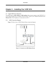
Chapter 2 - Your VOIP ATA at a glance
The VOIP ATA may have different ports and LEDs. Let’s take a look at the different options.
Depending upon your model, it may have some or all of the features listed below
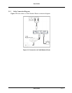
2.1 Ports and buttons
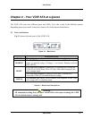
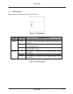
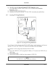
Fig 2-1 shows the back panel of the VOIP ATA.
Figure 2-1 : Back Panel
DESCRIPTIONS
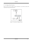
12V DC
This is where you will connect the included power adapter.
MODEM
The MODEM port allows you to connect the VOIP ATA to your
router or gateway using a Category 5 (or better) Ethernet network
cable (RJ-45).
Press and hold the RESET button for 2 to 4 seconds will restore the
VOIP ATA’s WAN Static IP to 192.168.1.200 while keeping all the
other settings intact.
RESET
Press and hold the RESET button for more than 5 seconds will
restore the VOIP ATA to default factory settings.
PHONE
The PHONE port allows you to connect your telephone to the VOIP
ATA using a RJ-11 telephone cable.
Table 2-1 : Back Panel Descriptions
Warning!
All custamized setting that you have saved will be lost upon resetting the VOIP
ATA to default factory settings will