


User Guide
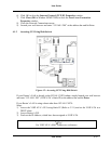
User Guide 2-9
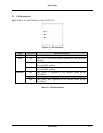
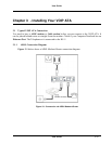
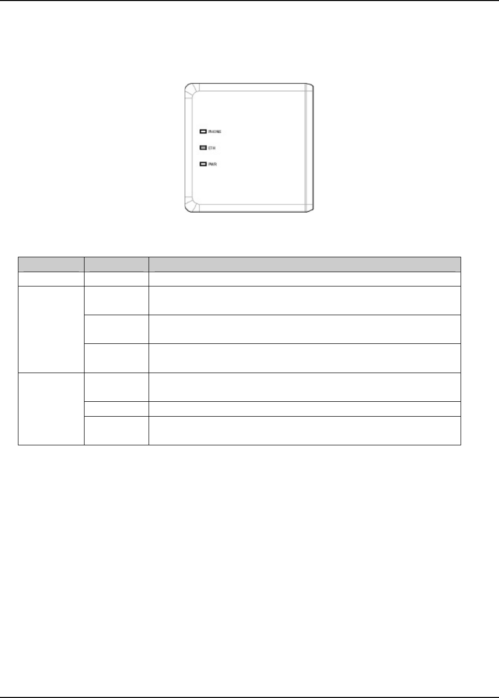
2.2 LED description
Fig 2-2 shows the LED indicators of the VOIP ATA.
Figure 2-2 : LED Indicators
LED
STATUS
DESCRIPTIONS
PWR
On
The VOIP ATA is receiving power.
On
The VOIP ATA has an Ethernet connection with cable/DSL
modem.
Blinking
The VOIP ATA is sending/receiving dVoIP ATA to/from
the cable/DSL modem.
ETH
Off
The VOIP ATA doesn’t have an Ethernet connection with
the cable/DSL modem.
On
This port(s) is registered to the Internet Phone Service
Provider(s).
Blinking
The telephone(s) connected to this port(s) is(are) off-hooked.
PHONE
Off
This port(s) isn’t registered to the Internet Phone Service
Provider(s).
Table 2-2 : LED Descriptions