


Module Components
2-2 Installing the DIGITAL VNswitch 900GV
Module Components
The following sections describe the front and back panel components for the DIGITAL
VNswitch 900GV module.
For more information about the module’s LEDs, refer to Appendix A.
Front Panel Components
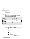
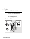
Figure 2-1 shows the front panel components and Table 2-1 describes them.
Figure 2-1: Front Panel LEDs and Connectors
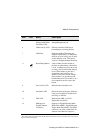
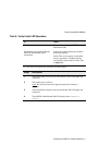
Table 2-1: Front Panel LEDs and Connectors
Item Icon Name Description
1 Power LED Lights when the module has power.
2 Module OK
LED
Lights when the module passes self-test.
3 VNbus Status
LED
Shows if the module is properly attached
to a VNbus backplane.
1
4 VNbus
Activity LED
Indicates network traffic.
1
(continued on next page)
NPB-1070-98F
8
7
5
6
3
4
1
2 9
1211
10