


Module Components
2-4 Installing the DIGITAL VNswitch 900GV
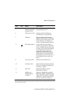
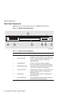
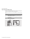
Back Panel Components
Figure 2-2 shows the front panel components and Table 2-2 describes them.
Figure 2-2: Back Panel Components
Table 2-2: Back Panel Components
Item Name Description
1 Locking tab Locks the module into a MultiSwitch 900
backplane. Contains the hot-swap switch lever.
2 48-pin connector Provides network and power connections to the
module when the module is installed in a
MultiSwitch 900.
3 Grounding bolt Provides a chassis grounding connection
between the module and the MultiSwitch 900.
4 Manufacturing label Lists the module’s part number, serial number,
revision level, and power requirements.
5 160-pin connector Provides network and power connections to the
module when the module is installed into a
MultiSwitch 900.
6 Mounting tab Secures the module when it is installed into a
MultiSwitch 900.
7 Grounding fingers Provide additional chassis grounding between
the module and a MultiSwitch 900.
234
5
6
1
7
NPB-9723-95F