


Installing the DIGITAL VNswitch 900GV 2-3
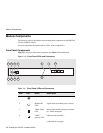
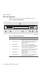
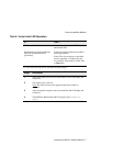
Module Components
1
The VNbus Status and Traffic LEDs display different indications during a load state. Refer to the release
notes for current descriptions.
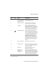
Item Icon Name Description
5 Load/Dump/
Management(LDM)
Port Status LED
Indicates the link status of the Load/
Dump/Management port.
6 LDM Activity LED Indicates when the LDM port is
transmitting or receiving packets.
7 LDM Port Dedicated 10BaseT Ethernet port.
Supports upline dump. (A dump entry
must be set up in config_acct in order
for the dump to occur.) This port is
wired as a straight-through connector.
8 Reset/Dump Button Used to either reset the module or
perform an upline dump, followed by
a reset. (A dump entry must be set up
in config_acct in order for the dump to
occur.) If this button is pressed as
operational code initializes, the
module will reset to current settings.
If the module is in operation mode,
hold the button for five seconds. Use a
non-conductive device to press the
button.
9 Port Activity LED Indicates network traffic level.
10 Port Status LED Shows the status of the ports. Indicates
if the port is enabled or disabled and
receiving a valid link.
11 FRU LED Indicates the GBIC is a Field
Replacable Unit (FRU).
12 MMI port for
Gigabit Ethernet
connectors
Support for Gigabit Ethernet Multi-
Mode Fiber (MMF), Gigabit Ethernet
Single-Mode Fiber (SMF). The GBIC
connectors are color coded: black for
shortwave and blue for longwave.