


NTI UNIMUX SERIES USB KVM SWITCH
6
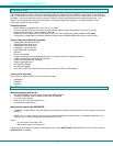
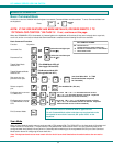
5. When cascading switches, follow the instruction on page 29 for "Cascading".
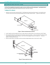
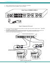
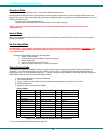
6. Connect the AC line cord to the UNIMUX. (See Fig. 5 below.)
Figure 5- Connect the AC line cord
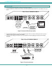
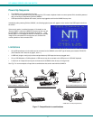
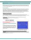
7. Connect each CPU to the USB switch using a USBVEXT-xx-MM video and input device interface cable – REQUIRED
(not supplied). (See Fig. 6 below.)
8. Group the input device and monitor interface cables from each CPU, making sure that cables from the first CPU are
connected to the UNIMUX at connectors CPU 1 and VIDEO 1. Cables from the second CPU should
connect to CPU 2 and VIDEO 2 connectors...etc.
Figure 6- Connect each CPU
M O N IT O R
U S B D E V I C E S
C P U 4
C P U 3
C P U 2 C P U 1
C P U 8
C P U 7
C P U 6 C P U 5
8 4
7 3 6 2 5 1
V I D E OV I D E O
R
S
2
3
2
N E T W O R K T E C H N O L O G IE S
IN C
T e l: 3 3 0 - 5 6 2 -7 0 7 01 2 7 5 D a n n e r D r , A u r o r a , O H 4 4 2 0 2 w w w .n t i1 .c o m
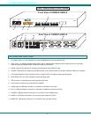
R e a r V i e w o f U N I M U X - U S B V - 8
I E C P o w e r c o r d
MONITOR 1
MONITOR 2
MONITOR 3
MONITOR 4
USER 1USER 2
USER 3USER 4
R
S
2
3
2
NTI
R
CPU 16
MONITOR 1
MONITOR 2
MONITOR 3
MONITOR 4
USER 1USER 2
USER 3USER 4
R
S
2
3
2
NTI
R
CPU 16
SLAVE #2 UNIMUX 4X16 SLAVE #1 UNIMUX 4X16
USBVEXT-
xx
-MM
USBVEXT-
xx
-MM
CONNECT MASTER CPU PORT 1
TO ONE USER PORT ON SLAVE1
CONNECT MASTER CPU PORT 2
ONE USER PORT ON SLAVE2
MONITOR
USB DEVICES
CPU 4 CPU 3 CPU 2 CPU 1
CPU 8 CPU 7 CPU 6 CPU 5
8 4 7 3 6 2 5 1
VIDEOVIDEO
R
S
2
3
2
NETWORKTECHNOLOGIES INC Tel:330-562-70701275 Danner Dr, Aurora, OH 44202 www.nti1.com
REAR VIEW OF MASTER (UNIMUX-USBV-8O)