


NTI UNIMUX SERIES USB KVM SWITCH
25
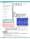
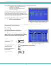
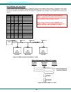
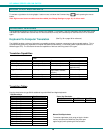
Unit Address and Loop Back
To allow multiple units to be controlled from a single CPU serial port, the RS232 control interface is designed to allow "daisy
chaining" up to 15 units. By setting the appropriate RS232 dip switches, each unit can be given a unique address (1-15). Then the
unit will only respond to commands on the bus if its address is embedded in the command. Use the table below to set the unit
address.
DIP SWITCH UNIT ADDRESS
8 7 6 5
OFF OFF OFF OFF 0 (not valid)
OFF OFF OFF ON 1
OFF OFF ON OFF 2
OFF OFF ON ON 3
OFF ON OFF OFF 4
OFF ON OFF ON 5
OFF ON ON OFF 6
OFF ON ON ON 7
ON OFF OFF OFF 8
ON OFF OFF ON 9
ON OFF ON OFF 10
ON OFF ON ON 11
ON ON OFF OFF 12
ON ON OFF ON 13
ON ON ON OFF 14
ON ON ON ON 15
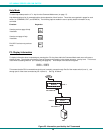
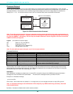
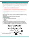
Figure 27- RS232 connection with Matrix-Y-1 cable
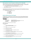
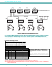
Figure 28- Pinout of Matrix-Y-1 cable
NTI
SWITCH
CPU
RS232
First Unit
NTI
SWITCH
RS232
NTI
SWITCH
RS232
Second Unit
Last Unit
RS232
Serial Port
Matrix-Y-1
Matrix-Y-1 Matrix-Y-1
(Unit #1)
(Source)
23
33
555
22
7
8
1
4
6
Jumper
Jumpers
Not connected to
source connector
(Unit #2)
9D Female9D Male 9D Male
Wiring Schematic of Matrix-Y-1 cable
Note: The "loop back" RS232 dip switch (RS232 dip
switch 1) should be ON for the last unit in the chain, and
OFF for all other units. If only one unit is being controlled,
the loop back dip-switch should be left ON.
Note: In order to connect multiple NODEMUX units
together a Matrix-Y-1 cable must be used. (See Fig. 27.)
See Fig. 28 for the pinout of the Matrix-Y-1 cable.