


NTI UNIMUX SERIES USB KVM SWITCH
5
INSTALLATION
1. It is not necessary to turn the CPUs or monitors OFF during this installation.
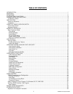
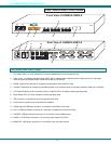
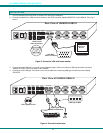
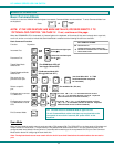
2. Connect the cable from a VGA multi-scan monitor to the 15HD connector labeled “MONITOR” on the UNIMUX (See Fig. 3
below.)
Figure 3- Connect a VGA multi-scan monitor
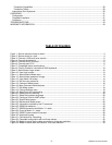
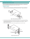
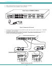
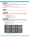
3. Connect the male USB type A connector on the keyboard cable to either one of the two USB type A female connectors
labeled "DEVICES" on the rear panel of the UNIMUX.
4. Connect the male USB type A connector on the mouse cable to the remaining USB type A female connector labeled
"DEVICES".
Figure 4- Connect the device(s)
V G A
M u l t i - S c a n
M o n i t o r
1 5 H D M a l e
V i d e o C o n n e c t o r
1 5 H D F e m a l e
V i d e o C o n n e c t o r
R e a r V i e w o f U N I M U X - U S B V - 8
M O N IT O R
U S B D E V I C E S
C P U 4
C P U 3
C P U 2 C P U 1
C P U 8
C P U 7
C P U 6 C P U 5
8 4
7 3 6 2 5 1
V I D E OV I D E O
R
S
2
3
2
N E T W O R K T E C H N O L O G IE S
IN C
T e l: 3 3 0 - 5 6 2 -7 0 7 01 2 7 5 D a n n e r D r , A u r o r a , O H 4 4 2 0 2 w w w .n t i1 .c o m
U S B K e y b o a r d
U S B
M o u s e
U S B T y p e A
M a l e C o n n e c t o r s
U S B T y p e A M a l e
R e a r V i e w o f U N I M U X - U S B V - 8
M O N IT O R
U S B D E V I C E S
C P U 4
C P U 3
C P U 2 C P U 1
C P U 8
C P U 7
C P U 6 C P U 5
8 4
7 3 6 2 5 1
V I D E OV I D E O
R
S
2
3
2
N E T W O R K T E C H N O L O G IE S
IN C
T e l: 3 3 0 - 5 6 2 -7 0 7 01 2 7 5 D a n n e r D r , A u r o r a , O H 4 4 2 0 2 w w w .n t i1 .c o m
U S B T y p e A F e m a l e