


NTI UNIMUX SERIES USB KVM SWITCH
3
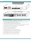
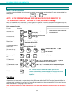
FEATURES AND FUNCTIONS
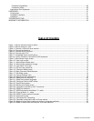
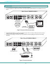
1. CPU Status LEDs- for visual indication of connection between the user and a specific CPU.
2. Daisy In/Out - for attaching interface cables (REXT-SR-xx) between slave switches and the master switch (only necessary
when connected to UNIMUX-USBV-xO switches made prior to 9/22/04)
3. RS232- (optional) Dip switches for configuring switch address when RS232 is used
4. Cascade- Dipswitches for configuring cascaded switches (only necessary when connected to switches made prior to 9/22/04)
5. CPU Select Switches- push to manually switch to a specific CPU or change the switch operating mode
6. Mode Status LEDs- for visual indication of switch operating mode
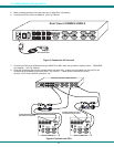
7. IEC Connector- for attachment of country-specific power cord
8. Power Switch- to power up or power down the UNIMUX
9. RS232-(optional) 9DB male connector- for attachment of RS232 control cable
10. CPU x- USB type B female connector-for connection of USB device cable from CPU(s)
11. DEVICES- USB type A female connector- for connection of user USB device(s)
12. VIDEO-x- 15HD female connectors- for connecting video cables from CPUs
13. MONITOR- 15HD female connector- for connection of the user video monitor
F E A T U R E S A N D F U N C T I O N S
1 8
1
8
C a s c a d eR S 2 3 2
O n
O f f
N T I
R
Netw ork Technologies Inc
S c a n
C o m m a n dB r o a d c a s t
1 2 3 4
U N I M U X
T M
5 6 7 8
D a is y
I n
D a is y
O u t
1
2 3 4 5 6
F r o n t V i e w o f U N I M U X - U S B V - 8
M O N IT O R
U S B D E V I C E S
C P U 4
C P U 3
C P U 2 C P U 1
C P U 8
C P U 7
C P U 6 C P U 5
8 4
7 3 6 2 5 1
V I D E OV I D E O
R
S
2
3
2
N E T W O R K T E C H N O L O G IE S
IN C
T e l: 3 3 0 - 5 6 2 -7 0 7 01 2 7 5 D a n n e r D r , A u r o r a , O H 4 4 2 0 2 w w w .n t i1 .c o m
7 8
9
1 0
1 1 1 2
1 3
R e a r V i e w o f U N I M U X - U S B V - 8