


NTI UNIMUX SERIES USB KVM SWITCH
31
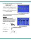
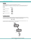
CASCADING
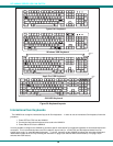
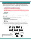
The UNIMUX-USBV-x USB KVM switch can be cascaded as shown in Fig. 31 below. Single user and multi-user UNIMUX
switches may be connected downstream (see Figs.33 and 34). The first switch in a cascaded system is referred to as the
"master", while all downstream switches are referred to as "slaves". The only additional hardware required to cascade switches is
a set of device and monitor cables for each “SLAVE UNIT” (see MATERIALS on page 1). All CPUs and switches can then be
controlled by users using OSD commands with Command Mode.
Notes:
• The UNIMUX USB KVM switch must have OSD installed to use cascading.
• Cascading is not an option in the UNIMUX-USBV-2 2 port USB KVM switch
• If the UNIMUX-USBV-x is connected in a cascaded system with earlier UNIMUX-USBV-x switches (product made
prior to 10-1-04), then the dipswitches must be configured as indicated on page 30 and REXT-SR-xx cables must be
used as shown in figure 28.
• Slaves in a cascaded system must be either all single-user switches or all multi-user switches, but not a
combination of both.
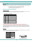
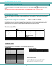
Configuration
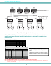
In a cascaded system with single-user switches as slaves, if all switches being cascaded were made on or after 10-1-04, then no
additional configuration is necessary. If any single-user switches in the cascaded system were made prior to 10-1-04, then all
units must be configured using the 6-position dip switch (located on the front of each unit) according to the tables on page 32
(Table 1 and Table 2).
A cascaded system using multi-user switches as slaves requires no additional configuration.
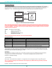
Cascaded Installation
a. Follow the instruction under Configuration above before proceeding.
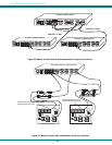
b. Using the 15HD video cable ends of a USBVEXT-xx-MM cable, connect the USB KVM slave's MONITOR port to the master’s
VIDEO 1 port.
c. Using the USB ends of the same USBVEXT-xx-MM cable, connect one of the USB slave’s USB DEVICES ports to the
master’s CPU 1 port.
Note: Only one of the two ports labeled DEVICES on a slave needs to be used in order for cascading to work.
d. Repeat step b. & c. for each additional slave, keeping in mind that each slave will connect to the next available master’s
port (i.e. Slave #2 to master’s VIDEO 2 & CPU 2, etc.) See Fig. 33 on page 33.
e. With a RMT extension cable, connect the master’s DAISY OUT port to slave #2’s DAISY IN port. Then connect slave #2’s
DAISY OUT to slave #3's DAISY IN. Continue until all slaves are connected together.
Figure 31- Connections for Cascading
( s l a v e u n i t 1 )
( s l a v e u n i t 2 )
( s l a v e u n i t 3 )
( m a s t e r u n i t )
R E X T - S R - x x
R E X T - S R - x x
R E X T - S R - x x
U S B - V E X T - x x M M
U S B V E X T - x x - M M
U S B
C P U
U N I M U X - U S B V - 8
U S B
C P U
U S B
C P U
U S B
C P U
U S B
C P U
U S B
C P U
U S B
C P U
U S B
C P U
U S B V E X T - x x - M M
U S B V E X T - x x - M M
U S B V E X T - x x - M M
U S B - V E X T - x x M MU S B - V E X T - x x M M
U N I M U X - U S B V - 8 U N I M U X - U S B V - 8
U N I M U X - U S B V - 8
The REXT-SR-xx cable shown is only required if
one or more slave switches was made prior to
10-1-04. Otherwise it may be omitted.