


43
to attenuate the antenna’s signal by placing a variable attenuator between the MSU’s
F-connector and the antenna. Note: Radio Shack offers a variable RF attenuator
which works very well with the IntelliControl. (RS15-578)
No LED lights = Indicates that the RF signals are not being transmitted from the
remote or received by the MSU.
Note: If you are experiencing RF interference (or no RF operation at all), remove the
antenna and place the tabletop remote 1/2” away from the antenna socket. If the Green
LED now lights when the “Channel Up” key is pressed (while a Master Key is selected),
the RF circuitry is working, but the antenna is picking up excessive interference. Attempt to
move the antenna or attenuate the antenna’s signal.
If the red LED lights only when buttons are pressed (without the antenna connected), you
may have the “Unit ID” code set incorrectly. Make sure that the DIP switch settings inside
the Tabletop Remote match those settings on the “Utilities” tab in the IntelliFile II software.
If the LED locks up red when the antenna is connected, the antenna is being “jammed”
with continuous interference. Eliminate the source of the interference, relocate the
antenna, or attenuate the antenna’s sensitivity (see below).
Note: Once again, Radio Shack offers an excellent Variable RF Attenuator (RS15-578). If
further attenuation solves the problem but delivers inadequate range you must either find
and deactivate the source of the interference, or special order an IntelliControl with
another frequency. Niles manufactures IntelliControls with an alternate RF frequency of
315 MHz (as opposed to the standard carrier frequency of 418 MHz). THESE UNITS ARE
MADE TO ORDER ONLY WITH THE APPROVAL OF THE TECHNICAL SUPPORT
DEPARTMENT. If you feel that your installation requires a 315 MHz IntelliControl, please
contact Niles Technical Support at 1(800)289-4434 for qualification and approval.
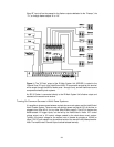
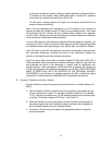
6. Connect Flashers and Sync Cables
Connect all flashers and sync connectors to the correct location on the Main System Unit
(MSU).
a. Label all cables for both the component they are connected to, and whether they are
IR, sync, interconnect, or power. For example, the flasher routed to the TV is labeled
“TV IR”, while the sync cable from a 12V wall adapter plugged into the switched outlet
of a Cable TV Decoder is labeled “CATV-Sync” (see Figure 12).
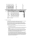
b. Attach the flashers to the front panel sensors of each component, and plug each of
the flasher plugs into the correct IntelliControl flasher connector that corresponds to
that component’s Master Key on the Tabletop Remote.
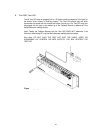
c. Connect the 12V and video sync cables to the appropriate jacks for all respective
source components.